9 Cases— Injection Mold Troubleshooting
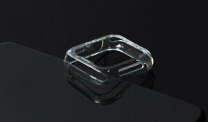
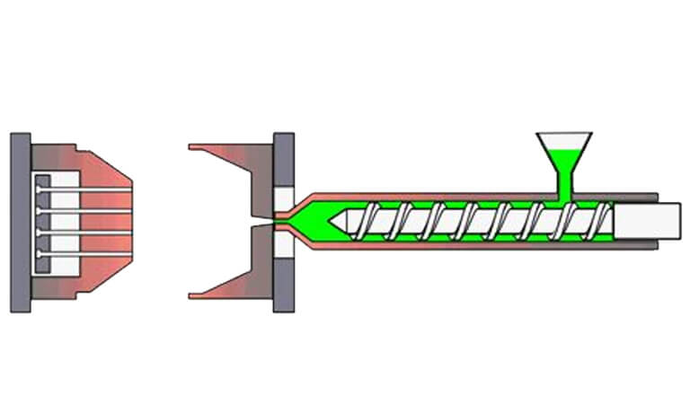
Injection mold is a tool for producing plastic products; it is also a tool for giving plastic products complete structure and precise dimensions. The structural form of the injection mold and the processing quality of the mold directly affect the quality and production efficiency of the plastic parts.
The most common and most common causes of injection mold failures and their troubleshooting methods in the production of injection molds and plastic products are described in detail as follows:
1. Difficulty in gate stripping
During the injection molding process, the gate sticks to the gate sleeve and is not easy to come out.
When the mold is opened, the product has crack damage. In addition, the operator must knock out the tip of the copper rod from the nozzle to loosen it before demoulding, which seriously affects the production efficiency.
The taper hole of the sprue sleeve is difficult to process, and standard parts should be used as much as possible. If you need to process it yourself, you should also make or buy a special reamer.
The taper hole needs to be ground to above Ra0.4. In addition, gate pulling rods or gate ejection mechanisms must be provided.
The guide post mainly plays a guiding role in the mold to ensure that the molding surfaces of the core and the cavity do not touch each other under any circumstances, and the guide post cannot be used as a force-bearing part or a positioning part.
In the following cases, when the injection is moved, the fixed mold will generate a huge lateral offset force:
(1). When the wall thickness of the plastic part is not uniform, the flow rate of the material passing through the thick wall is large, and a relatively large amount of pressure is generated here.
(2) The sides of the plastic parts are asymmetrical, such as the opposite sides of the mold with the stepped parting surface are not equal to the back pressure.
Due to the different charging rates in each direction, and the influence of the self-weight of the mold when the mold is installed, the dynamic and fixed mold offsets occur.
In order to solve the above problems, a high-strength positioning key is added on each of the four sides of the mold parting surface. The most convenient and effective way is to use a cylindrical key.
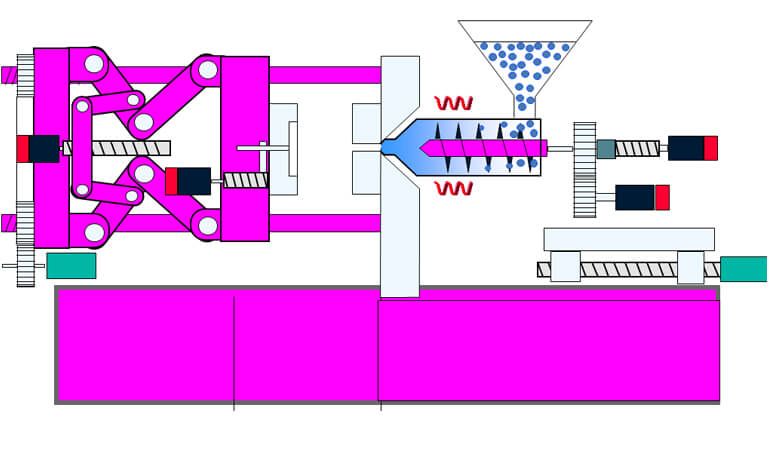
When the mold is injected, the molten plastic in the mold cavity generates a huge back pressure, generally 600~1000 kg/cm.
Mold manufacturers sometimes do not pay attention to this problem, and often change the original design size, or replace the moving template with low-strength steel plates.
Therefore, the moving formwork must be made of high-quality steel, with sufficient thickness, and low-strength steel plates such as A3 should not be used.
When necessary, support columns or support blocks should be set under the moving formwork to reduce the thickness of the formwork and improve the bearing capacity.
5.The ejector is bent, broken or leaking
The quality of the self-made ejector is better, but the processing cost is too high.
Now, standard parts are generally used, and the quality is poor.
If the gap between the ejector pin and the hole is too large, there will be leakage, but if the gap is too small, the ejector pin will be stuck due to the increase of mold temperature during injection.
What's more dangerous is that sometimes the ejector pin is pushed out of the normal distance, and the ejector pin does not move and breaks.
As a result, the exposed ejector pin cannot be reset and the die is damaged when the mold is closed next time.
In order to solve this problem, the ejector rod was re-ground, retaining a 10-15 mm mating section at the front end of the ejector rod, and the middle part was ground down by 0.2 mm.
6. Poor cooling or water leakage
The cooling effect of the mold directly affects the quality and production efficiency of the product, such as poor cooling, large shrinkage of the product, or uneven shrinkage and deformation of the warped surface.
On the other hand, the whole or part of the mold is overheated, so that the mold cannot be formed normally and the production is stopped.
The design and processing of the cooling system depends on the shape of the product. Do not omit this system because of the complex mold structure or difficult processing. Especially for large and medium-sized molds, the cooling problem must be fully considered.
7. The fixed distance tensioning mechanism fails
Fixed-distance tensioning mechanisms such as swing hooks and hasps are generally used in fixed mold core pulling or some secondary demolding molds.
Because such mechanisms are set in pairs on both sides of the mold, their actions must be synchronized, that is, When the mold is closed, the buckle is fastened at the same time, and the mold is opened to a certain position and the hook is released at the same time.
Once the synchronization is lost, it will inevitably cause the template of the drawn mold to be skewed and damaged.
The parts of these mechanisms must have high rigidity and wear resistance, and the adjustment is also difficult. The life of the mechanism is short.
When the core pulling force is relatively small, the method of pushing out the fixed mold by a spring can be used.
When the core pulling force is relatively large, the core sliding when the moving mold retreats, and the core pulling action is completed first and then the mold is split. Hydraulic cylinders can be used to pull cores on the mold.
The inclined pin angle A is large, and the advantage is that a large core pulling distance can be generated in a short mold opening stroke.
However, if the inclination angle A is too large, when the pulling force F is a certain value, the bending force P=F/COSA received by the inclined pin during the core-pulling process is also larger, and the inclined pin is prone to deformation and inclined hole wear.
At the same time, the upward thrust N=FTGA generated by the oblique pin on the slider is also greater, and this force increases the positive pressure of the slider on the guide surface in the guide groove, thereby increasing the frictional resistance when the slider slides.
It is easy to cause uneven sliding and wear of the guide groove. According to experience, the inclination angle A should not be greater than 25
8. Some molds are limited by the template area
If the length of the guide groove is too small, the slider will be exposed outside the guide groove after the core-pulling action is completed, which will easily cause the slider to tilt in the post-core-pulling stage and the initial stage of mold closing and reset.
The slider will be damaged or even damaged by bending. According to experience, after the slider completes the core pulling action, the length left in the chute should not be less than 2/3 of the total length of the guide groove.
When manufacturing a mold, it should be based on the requirements of the quality of plastic parts, the size of the batch, the requirements of the manufacturing period, etc.
which can not only meet the requirements of the product, but also the most simple and reliable in terms of mold structure, easy to process, so that the cost is low. Molds are great.
Custom Plastic Moulding Manufacturer/ WA:+86 13823302586 (gmolding.com)